ROCKET ELECTRONICS BAY
CONTROL, ORIENTATION, AND ONBOARD KINEMATIC ESTIMATION DEVICE (COOKED)
/ NDSU AIAA ROCKETRY TEAM /
CONTEXT
COOKED (Control, Orientation, and Onboard Kinematic Estimation Device) is an electronics bay I designed as part of NDSU's Rocketry Team. It features
a non-commercial sensor suite which logs data such as acceleration, velocity, and position.
Additionally, it hosts an onboard microcontroller (Teensy 4.1) which controls indicator lights and
a reactions wheel through PWM signals. Another microcontroller (ESP32) allows for remote authority over
MOSFETs which control power management.
In the fall of 2024, we restarted our university's rocketry team after years of dormancy. As no one on our team had prior model rocketry experience, the project became a full ground-up effort in learning how to design and build a model rocket from scratch. Ever since we restarted the project, I have been in charge of our electronics bay, which hosts our custom non-commercial sensors and other peripherals. Though I've had previous experience playing around with Raspberry Pis and Arduinos, this effort quickly presented its novel difficulties as the complete electrical package had to fit in a specified form factor.
In the fall of 2024, we restarted our university's rocketry team after years of dormancy. As no one on our team had prior model rocketry experience, the project became a full ground-up effort in learning how to design and build a model rocket from scratch. Ever since we restarted the project, I have been in charge of our electronics bay, which hosts our custom non-commercial sensors and other peripherals. Though I've had previous experience playing around with Raspberry Pis and Arduinos, this effort quickly presented its novel difficulties as the complete electrical package had to fit in a specified form factor.
DEVELOPMENT, ROUND 1 (2024-2025)
The development of the system (COOKED-1) is in response to the Space Grant Midwest High Powered Rocket Competition rules.
2024-2025 Competition:
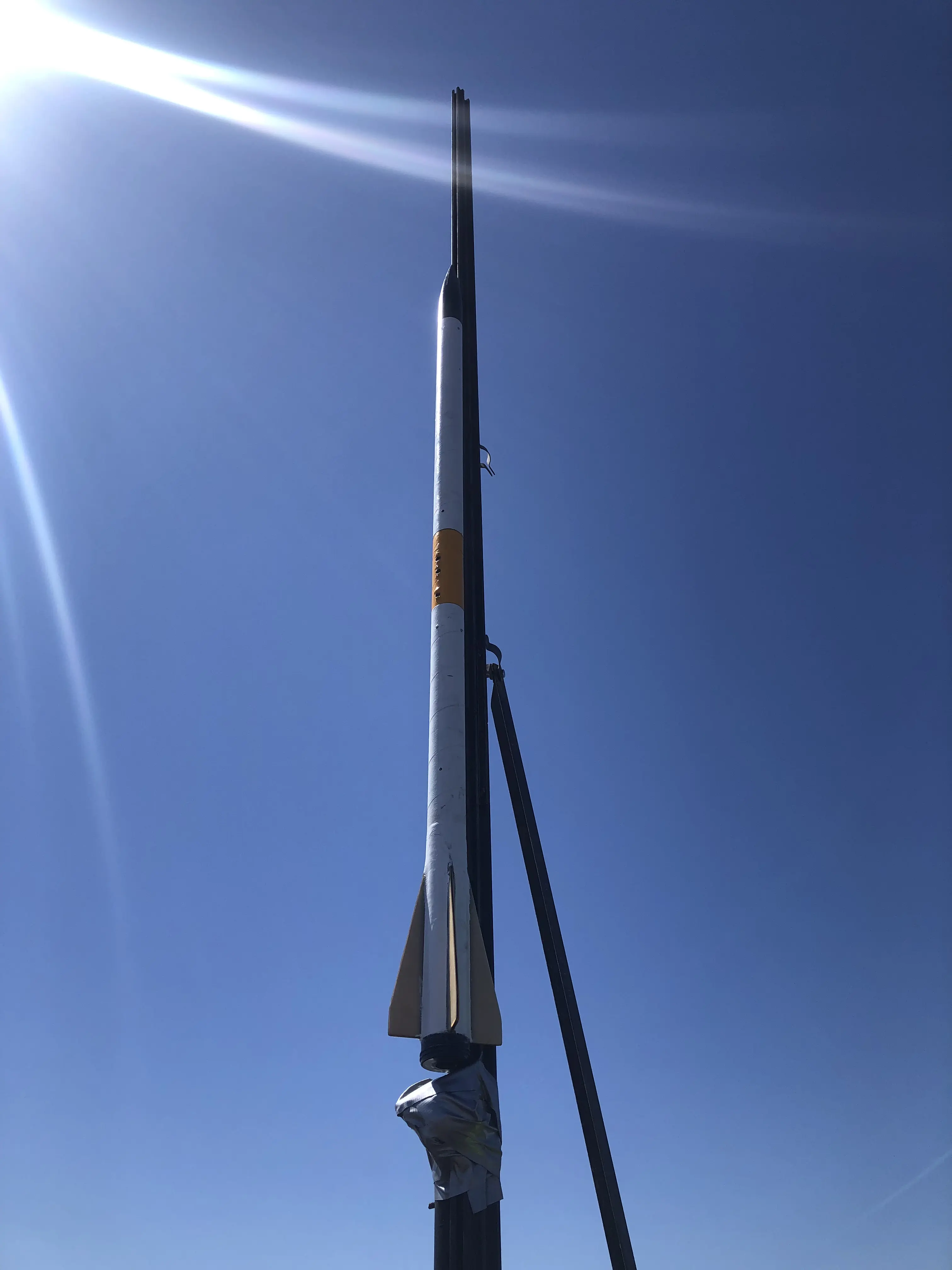
With the 1000 ft and max altitude requirement, we opted to build a miniumum diameter rocket, which is when the airframe diameter matches the motor diameter, minimizing drag and maximizing altitude. This constraint led to the electronic bay's maximum diameter to be around 1.9 inches. That fact would cause me much agony later on.
COMPONENT SELECTION (NON-COMMERCIAL SENSOR SUITE)
To select our components, we did online research on what other rocketry teams have used in the past. The Teensy 4.1 often surfaced, as it is exceptionally powerful due to its 600 MHz ARM Cortex-M7 processor, making it one of the fastest MCUs (microcontrollers) available. Additionally, it offers extensive I/O pins, which will be important due to the unknown number of needed peripherals for the whole system. For the IMUs, we had to account for the amount of g's the rocket would experience at launch. Because of this, we opted for a 9-DOF ICM20948 which is rated for ±16 g, and the ADXL375 which is rated for ±200 g. We went with these options as the other products we considered (such as the BNO055) were at either at their EOL or discontinued. For the barometer, we opted for a BMP390, though for future designs I would recommend a BMP581, as it sports 85% lower current consumption and 80% lower noise compared to the BMP390. For the GPS, we opted for the u-blox Neo M10.
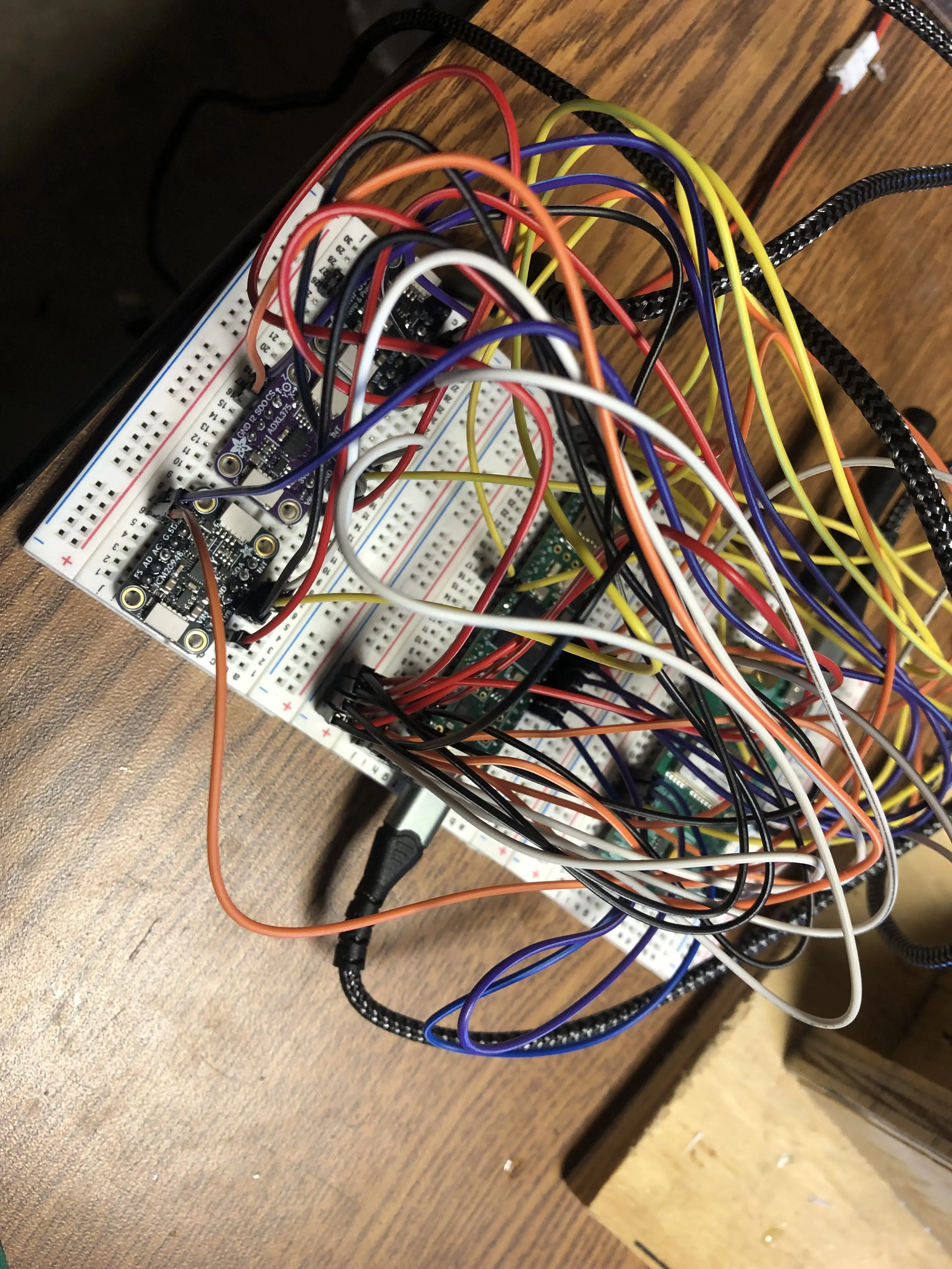
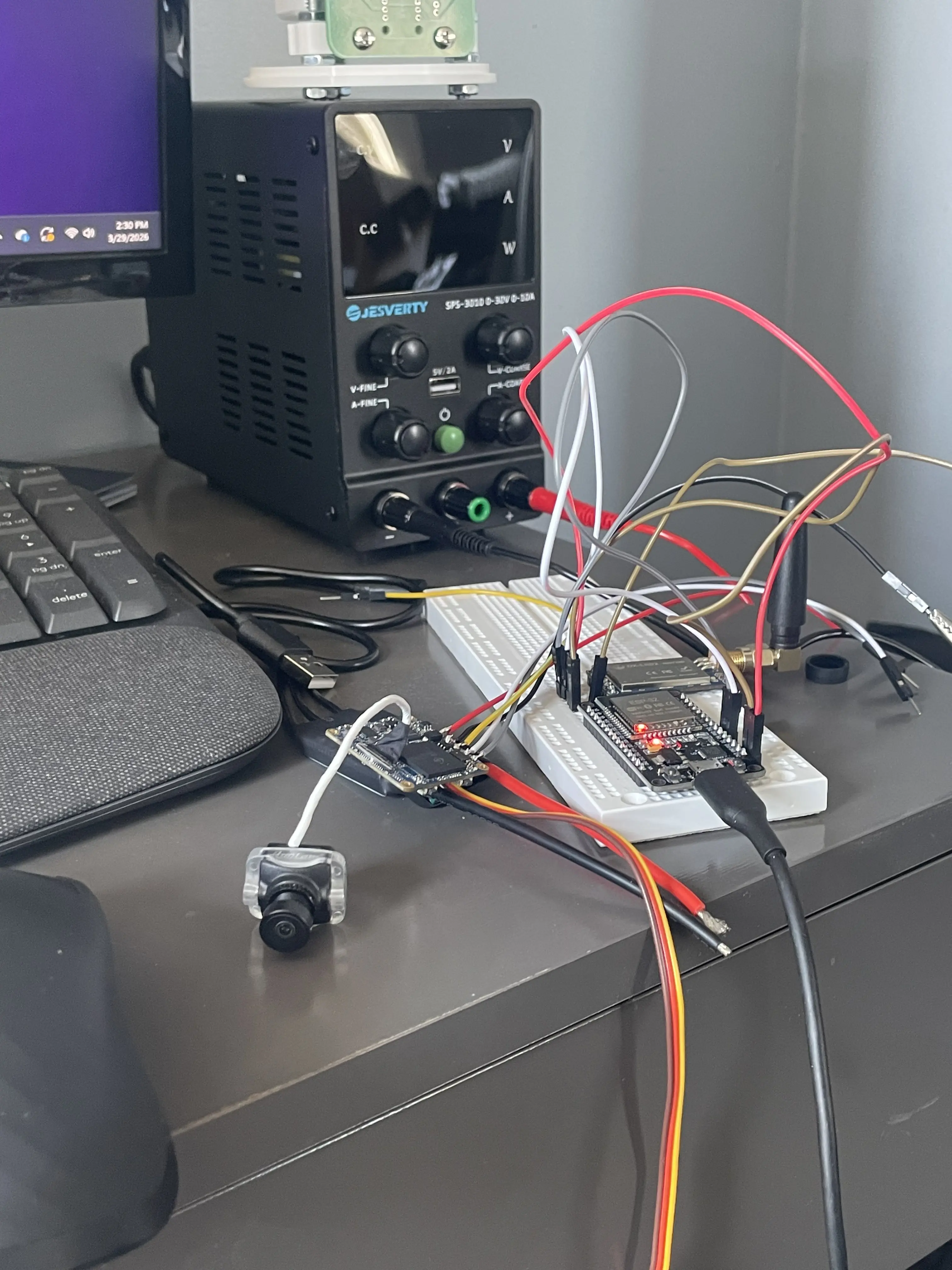
PROTOTYPING
To validate our component selection, I bought breakout boards and prototyped the circuit on a breadboard. I used VSCode with the PlatformIO extension, which is an open source ecosystem that developers use for embedded systems applications. It is much better than Arduino IDE as it offers library management and advanced debugging, concurrent with the IDE benefits of VSCode. I used pre-existing libraries to access data from each sensor and send it to the serial monitor on my Mac, which allowed me to validate the sensor data and identify any potential defects on the hardware. I had particular troubles with accessing the magnometers on the ICM20948, and the BMP390 consitently showed 0 pressure. The difficulty of the latter was likely a hardware issue, as replacing the sensor fixed the problem. While prototyping I learned about different hardware commumnication protocols such as SPI, I2C, and UART. The Neo M10, as with most GPS sensors, communicate to the MCUs via UART. Between SPI and I2C, I opted to use SPI for all the sensors since it operates at much higher speed (~80 MHz) than I2C (100-400 kHz), and this speed would be critical, particularly for the lift-off phase.
DESIGN
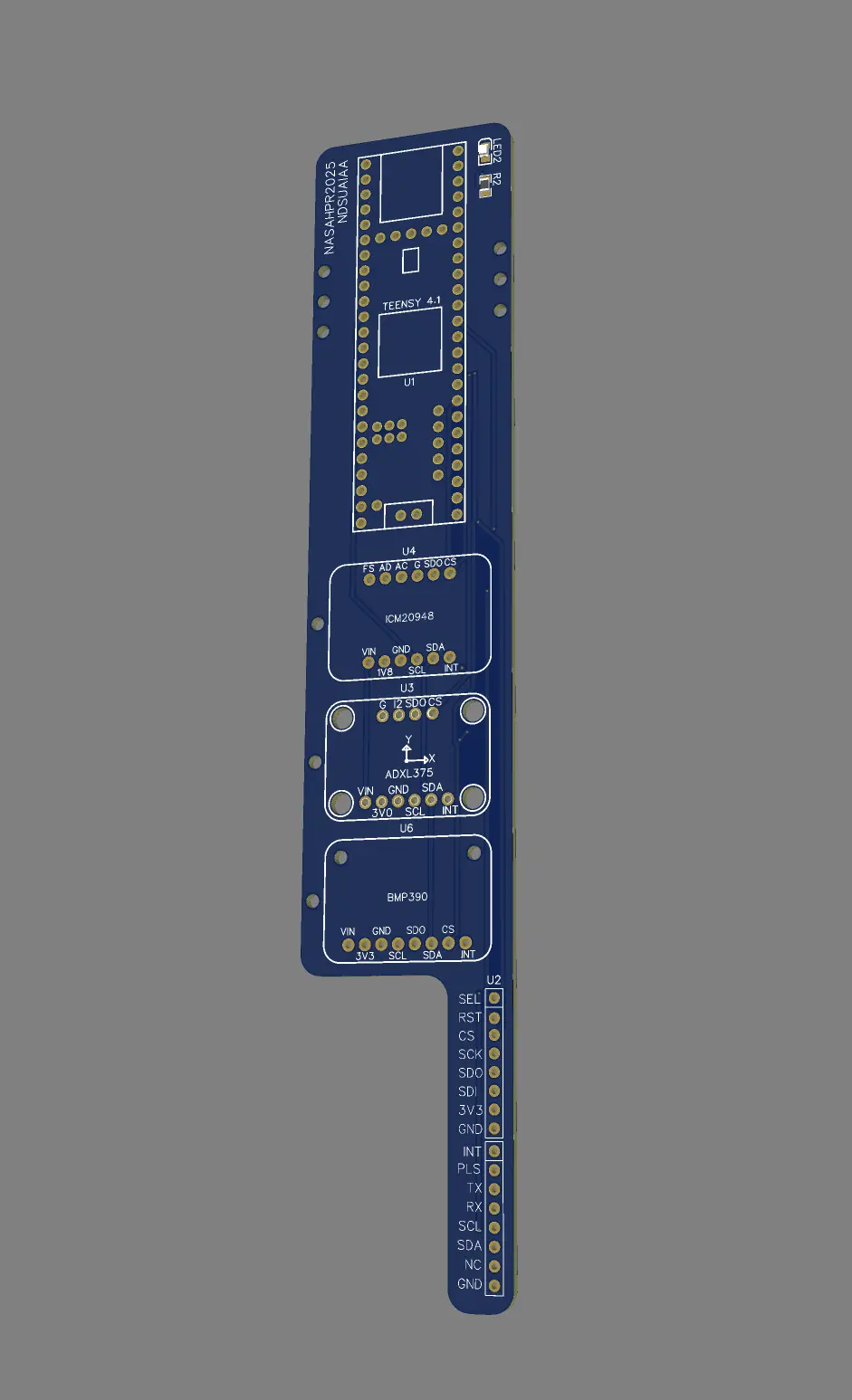
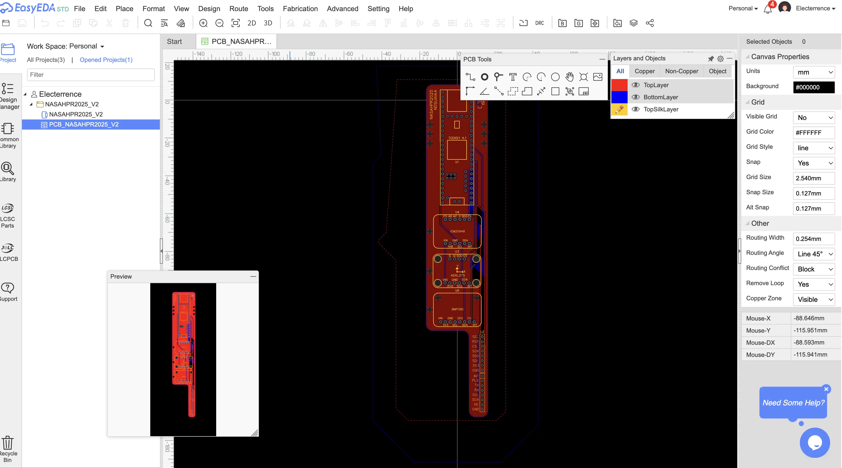
Fitting the non-commercial sensor suite in a 1.9 inch inner diameter body tube proved to be extraordinarily difficult. Cramming the sensors into the small tube meant wiring will get messy, and the risk of inadvertent wire pulls and cable strain increases. Additionally, the competition rules require onboard commercial sensors and supporting peripherals, such as our dual-deploy altimeter and batteries. To meet the spatial requirements, I determined that the best course of action was to design a printed circuit board (PCB), which I had never done before.
I played around with KiCad, which is a powerful, open source desktop application designed for complex PCB/electrical design projects. At this point, I had not taken an electrical engineering class yet, so I was not very familiar with electrical schematics. Eventually, I found out about EasyEDA, which is a simpler browser based tool. Though KiCad is much more powerful for complex circuits, EasyEDA provided a much more beginner friendly alternative, and it was "good enough" for my application. The first draft of my PCB was esentially just footprints of the MCU, IMUs, BMP, and the NEO M10 chip. After showcasing the gerber file to Jeff Erickson from NDSU's ECE department for review. There were two major issues:
I needed to redesign the PCB to account for these issues. Finding a breakout board for the GPS was particularly difficult as the size constraint meant I couldn't use any of the large u-blox boards. I was also blissfully unaware that the GPS chip needs an antenna, which I barely had the space for. The final board outline took on an abnormal shape which made space for our GPS.

THE INCIDENT
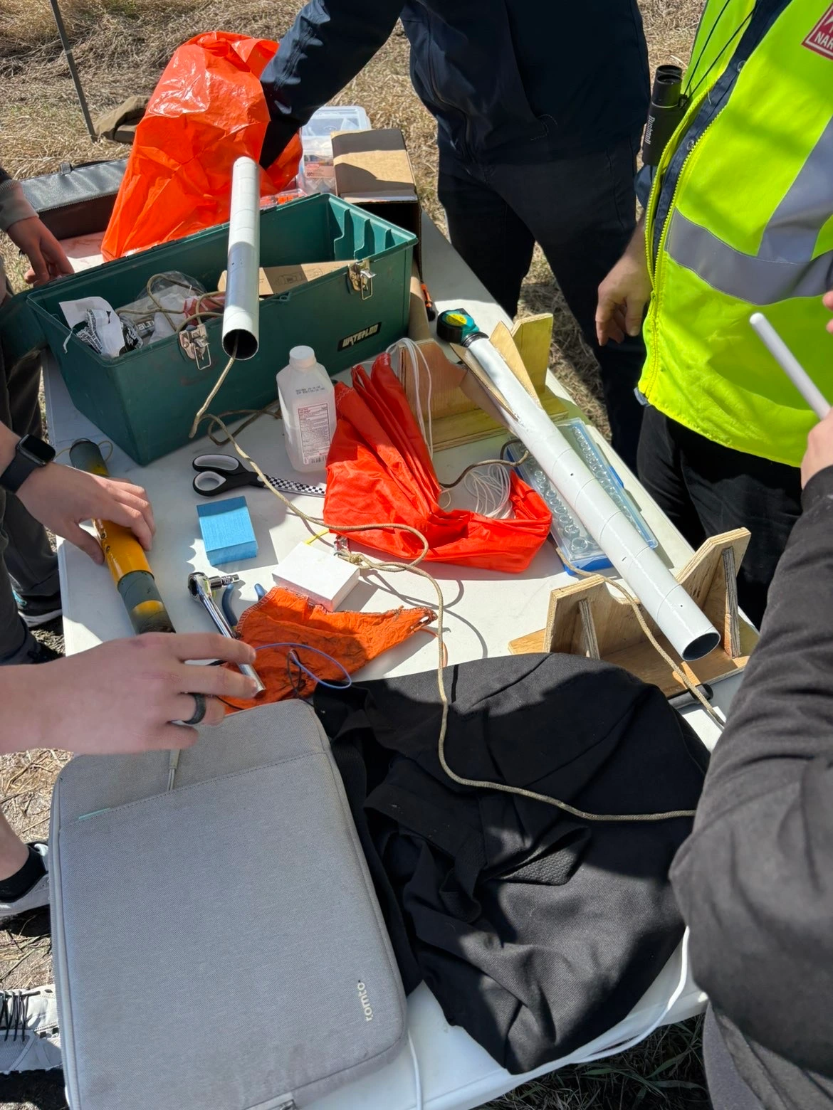
When test launch day arrived, my electronics bay was not yet ready for flight. We opted to launch without it, since we were more interested in testing the rocket itself (parachute deployment, etc.) rather than the electronics bay. The first phases of flight were successful, and the ejection charge deployed as intended. However, the charge burned through the wadding and damaged the parachute. When the parachute deployed, there was a hole in the canopy, and one of the suspension lines had been severed. The rocket struck the ground at high speed and was no longer usable for competition. With our budget nearly exhausted and finals quickly approaching, our campaign for the year came to an end, as we did not have the bandwidth to build another rocket. Despite this outcome, we still learned a lot about model rocketry design, manufacturing, and testing. I also gained valuable experience in working with embedded systems, designing PCBs, and sensor fusion for future projects.
2024-2025 Competition:
- 2 Flights: get to 1000 ft as close as possible, and max altitude
- Electronics bay with non-commercial sensors (like the ones used for Arduinos)
- Log in-flight acceleration, velocity, and position
With the 1000 ft and max altitude requirement, we opted to build a miniumum diameter rocket, which is when the airframe diameter matches the motor diameter, minimizing drag and maximizing altitude. This constraint led to the electronic bay's maximum diameter to be around 1.9 inches. That fact would cause me much agony later on.
COMPONENT SELECTION (NON-COMMERCIAL SENSOR SUITE)
To select our components, we did online research on what other rocketry teams have used in the past. The Teensy 4.1 often surfaced, as it is exceptionally powerful due to its 600 MHz ARM Cortex-M7 processor, making it one of the fastest MCUs (microcontrollers) available. Additionally, it offers extensive I/O pins, which will be important due to the unknown number of needed peripherals for the whole system. For the IMUs, we had to account for the amount of g's the rocket would experience at launch. Because of this, we opted for a 9-DOF ICM20948 which is rated for ±16 g, and the ADXL375 which is rated for ±200 g. We went with these options as the other products we considered (such as the BNO055) were at either at their EOL or discontinued. For the barometer, we opted for a BMP390, though for future designs I would recommend a BMP581, as it sports 85% lower current consumption and 80% lower noise compared to the BMP390. For the GPS, we opted for the u-blox Neo M10.
PROTOTYPING
To validate our component selection, I bought breakout boards and prototyped the circuit on a breadboard. I used VSCode with the PlatformIO extension, which is an open source ecosystem that developers use for embedded systems applications. It is much better than Arduino IDE as it offers library management and advanced debugging, concurrent with the IDE benefits of VSCode. I used pre-existing libraries to access data from each sensor and send it to the serial monitor on my Mac, which allowed me to validate the sensor data and identify any potential defects on the hardware. I had particular troubles with accessing the magnometers on the ICM20948, and the BMP390 consitently showed 0 pressure. The difficulty of the latter was likely a hardware issue, as replacing the sensor fixed the problem. While prototyping I learned about different hardware commumnication protocols such as SPI, I2C, and UART. The Neo M10, as with most GPS sensors, communicate to the MCUs via UART. Between SPI and I2C, I opted to use SPI for all the sensors since it operates at much higher speed (~80 MHz) than I2C (100-400 kHz), and this speed would be critical, particularly for the lift-off phase.
DESIGN
Fitting the non-commercial sensor suite in a 1.9 inch inner diameter body tube proved to be extraordinarily difficult. Cramming the sensors into the small tube meant wiring will get messy, and the risk of inadvertent wire pulls and cable strain increases. Additionally, the competition rules require onboard commercial sensors and supporting peripherals, such as our dual-deploy altimeter and batteries. To meet the spatial requirements, I determined that the best course of action was to design a printed circuit board (PCB), which I had never done before.
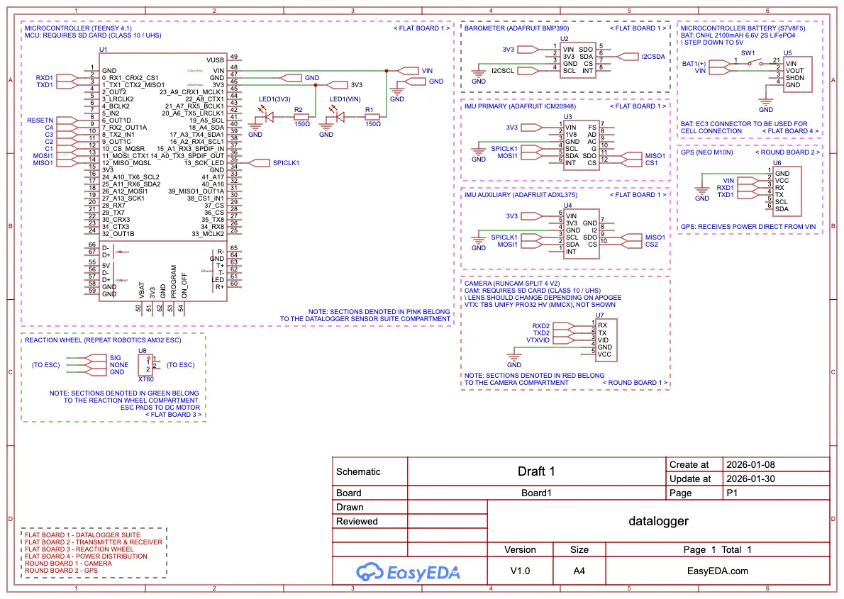
I played around with KiCad, which is a powerful, open source desktop application designed for complex PCB/electrical design projects. At this point, I had not taken an electrical engineering class yet, so I was not very familiar with electrical schematics. Eventually, I found out about EasyEDA, which is a simpler browser based tool. Though KiCad is much more powerful for complex circuits, EasyEDA provided a much more beginner friendly alternative, and it was "good enough" for my application. The first draft of my PCB was esentially just footprints of the MCU, IMUs, BMP, and the NEO M10 chip. After showcasing the gerber file to Jeff Erickson from NDSU's ECE department for review. There were two major issues:
- Lack of a copper ground pour (needed for a number of reasons)
- We did not have the direct capability to mount SMDs (such as our GPS and the tiny little LEDs I chose)
I needed to redesign the PCB to account for these issues. Finding a breakout board for the GPS was particularly difficult as the size constraint meant I couldn't use any of the large u-blox boards. I was also blissfully unaware that the GPS chip needs an antenna, which I barely had the space for. The final board outline took on an abnormal shape which made space for our GPS.
THE INCIDENT
When test launch day arrived, my electronics bay was not yet ready for flight. We opted to launch without it, since we were more interested in testing the rocket itself (parachute deployment, etc.) rather than the electronics bay. The first phases of flight were successful, and the ejection charge deployed as intended. However, the charge burned through the wadding and damaged the parachute. When the parachute deployed, there was a hole in the canopy, and one of the suspension lines had been severed. The rocket struck the ground at high speed and was no longer usable for competition. With our budget nearly exhausted and finals quickly approaching, our campaign for the year came to an end, as we did not have the bandwidth to build another rocket. Despite this outcome, we still learned a lot about model rocketry design, manufacturing, and testing. I also gained valuable experience in working with embedded systems, designing PCBs, and sensor fusion for future projects.
DEVELOPMENT, ROUND 2 (2025-2026)
New year, new rocket! The 2025-2026 competition objectives in terms of the datalogger were largely the same.
However, there were some interesting additions:
2025-2026 Competition:
After reading these new requirements, I was slightly horrified. The vision portion meant I would need to somehow implement cameras onboard the rocket with a high enough framerate and resolution to capture the light changes on the ground, and possibly use specialized computer vision algorithms to decode the pattern. The roll mechanism was especially frightening, since that meant my datalogger is no longer just a monitoring unit, but it also now has direct authority over the rocket's trajectory, as my orientation data would be needed to satisfy the roll mechanism necessity. Since the sensors from the year prior were already proven to work, I reused the same set. This would lay the groundwork for COOKED-2.
CONCEPT GENERATION
The prior year's electrical bay conditions were quite straightforward, as the datalogging requirements were clearly outlined. With the new roll mechanism and camera requirement, we needed to think of new rocket subsystems that will couple with the datalogger. We considered two main possibilities for the roll mechanism:
Online research leaned us toward the reaction wheel, as controlled fin setups could prove jittery and therefore unreliable. A reaction wheel could be contained in the internal volume of the rocket, and only relies on one control input (speed of the driving motor). This meant we needed an appropriately sized motor, ESC, and flywheel. The Teensy 4.1 can send out PWM signals to the ESC and control the motor speed. For the cameras, online forums largely pointed to the Mobius or RunCam cameras. We opted for the RunCam Split V2 due to its form factor, as it has a free floating lens attached to a board which we can interface directly with.
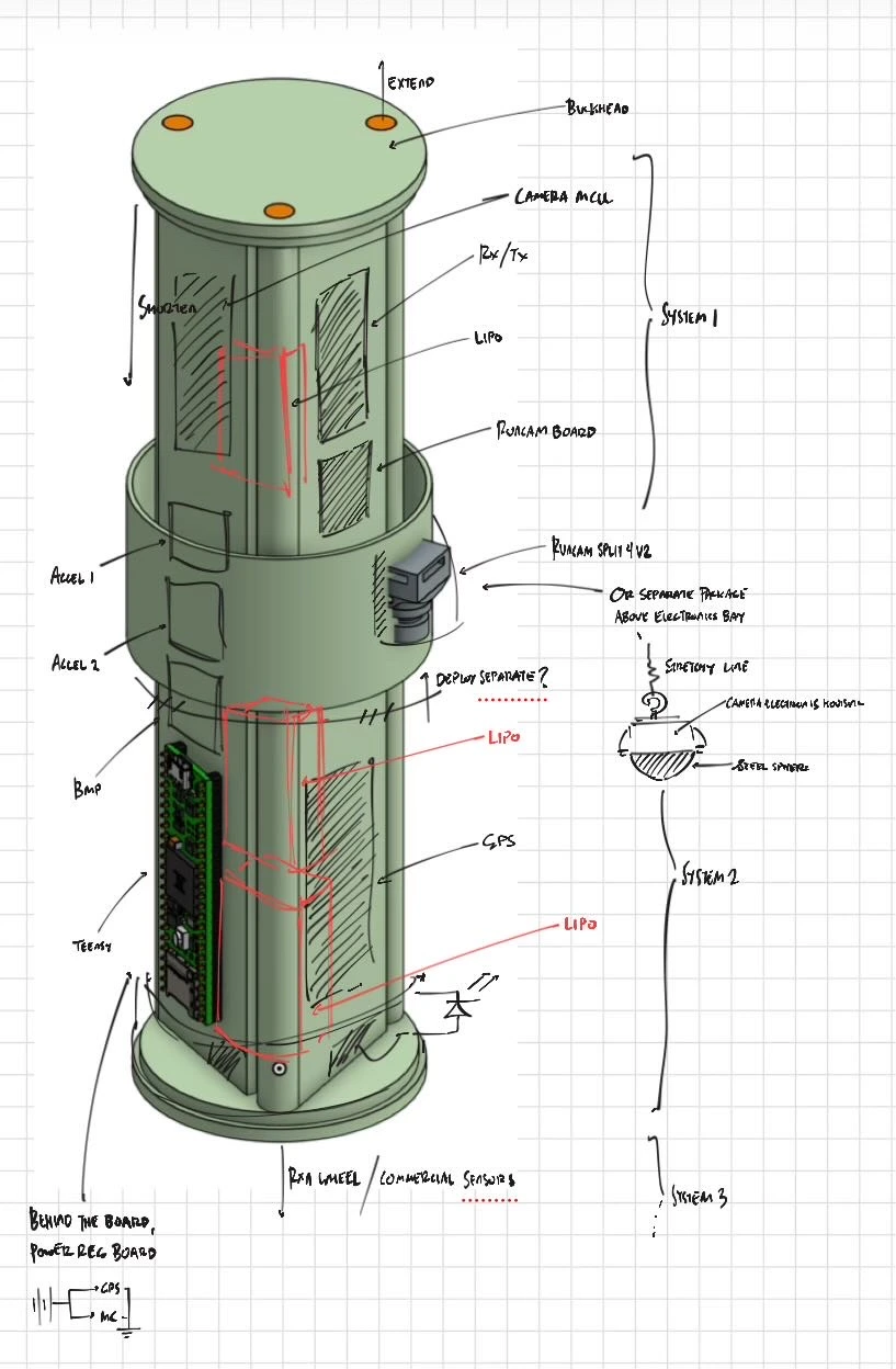
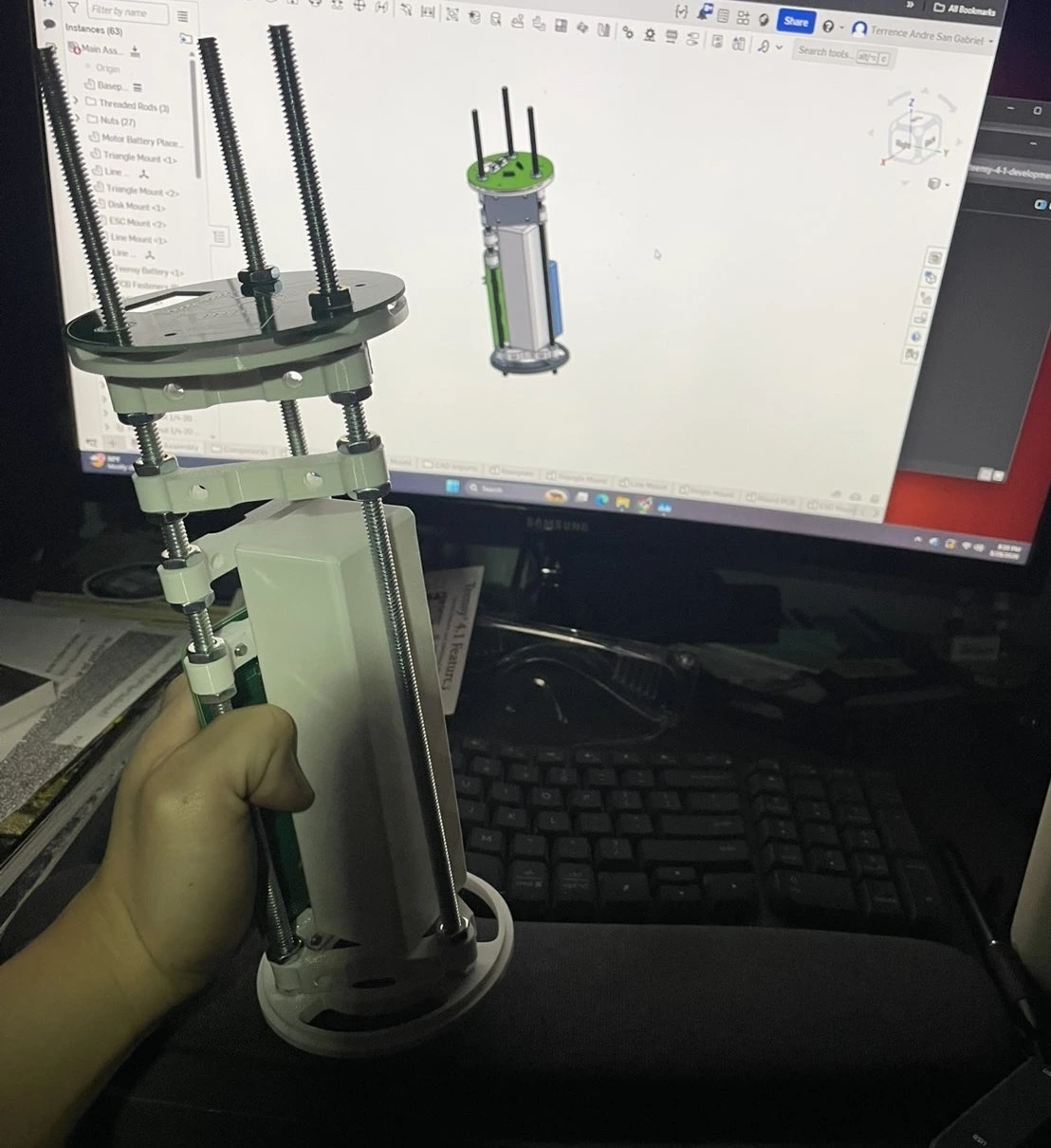
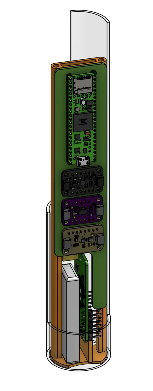
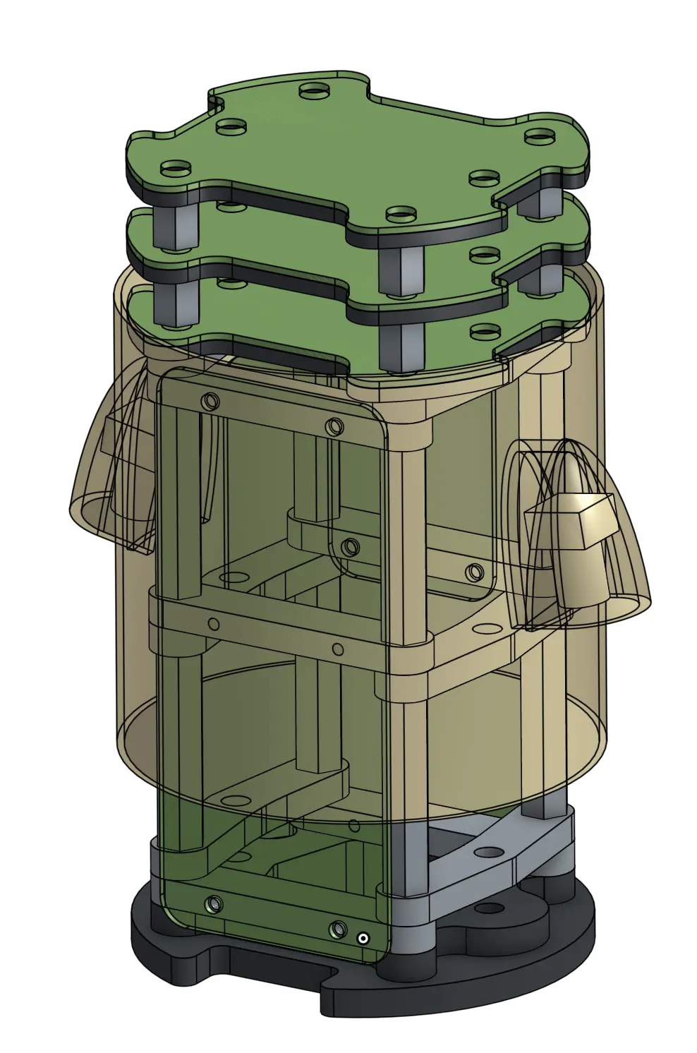
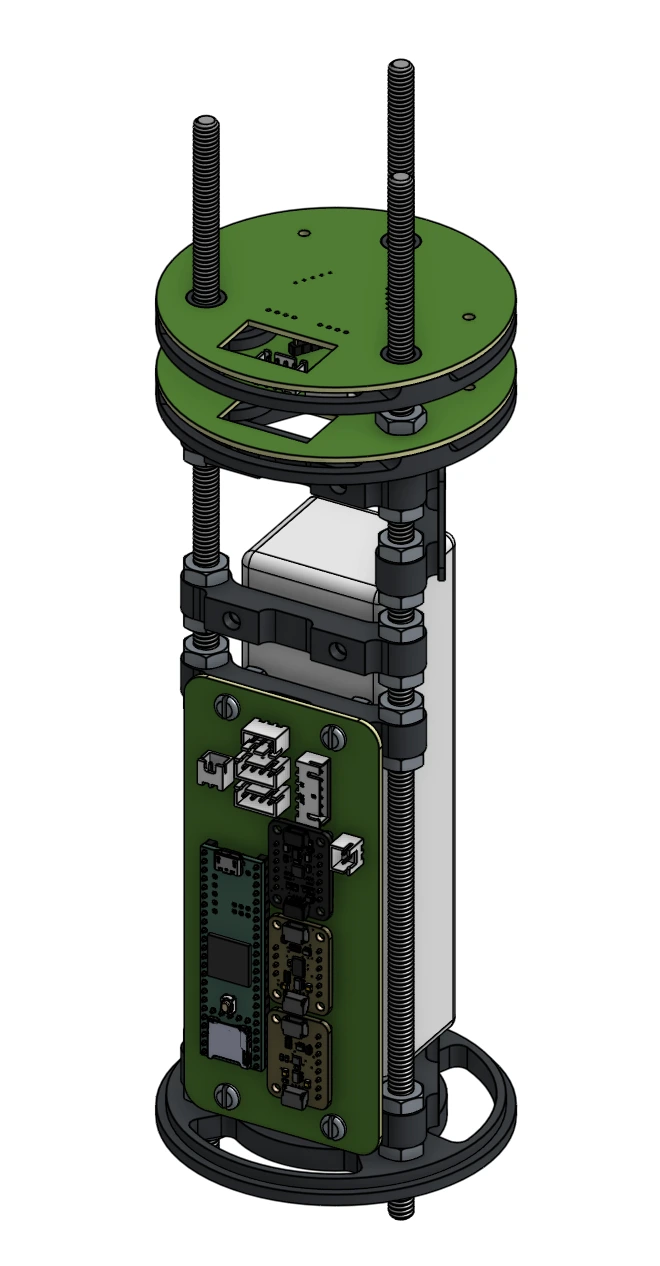
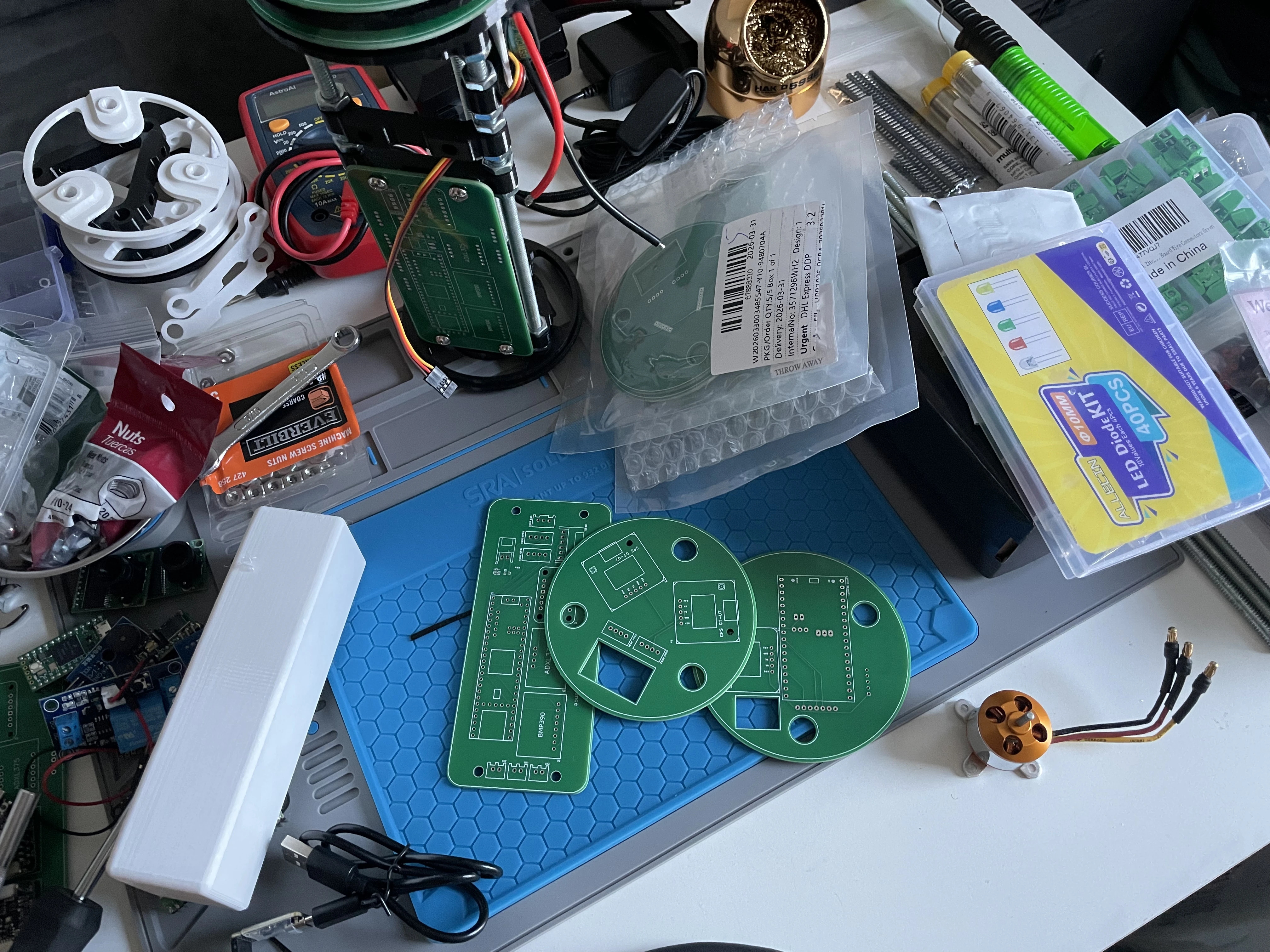
STRUCTURAL MOUNTS
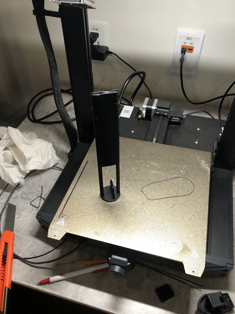
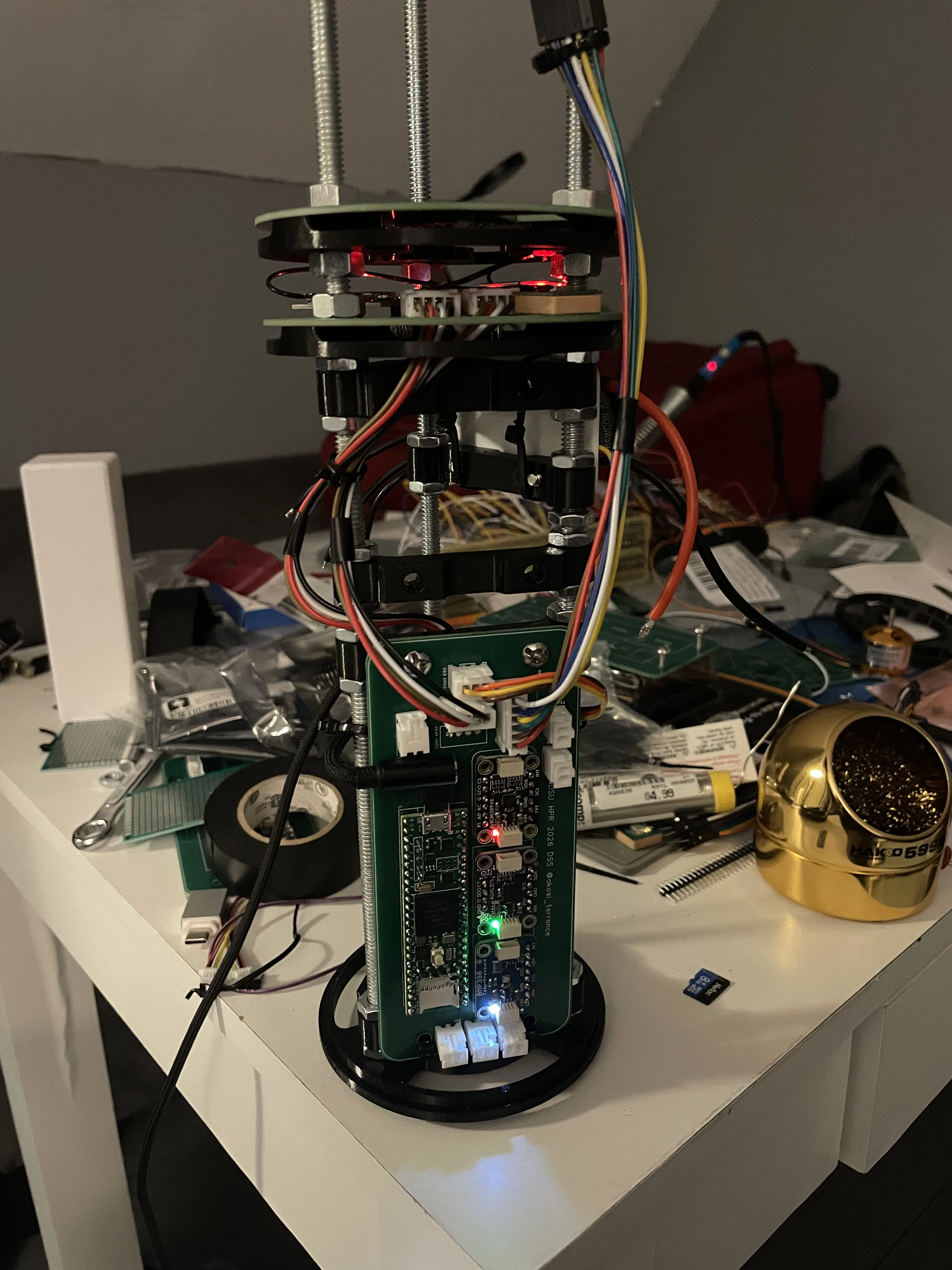
The old datalogger PCB was a simple board that connected multiple sensor breakout boards to the MCU. This year, I wanted to leverage JST connectors to couple across different custom PCBs. They are vibration resistant and are advantageous for high dynamic environments, such as the case for a model rocket. At first, I wanted to use a set of 4 threaded rods in a square configuration to mount 4 separate boards. However, I later switched to a 3 rod triangle configuration, since it would make the most amount of sense for the 3 cameras we were using. Additionally, I added support for disc PCBs above the main boards for peripherals that won't directly fit on the main PCB. The empty volume in the middle of the rods are reserved for the LiPo batteries to be used for the flywheel motor and the electronics. I printed the mounts with PETG due to its high impact resistance, and secured them with hex nuts.
POWER MANAGEMENT
Since the rocket may be sitting idle on the pad for a while before it actually launches, I do not want the datalogger and cameras to consume power until right before launch. This meant I needed a way to either automatically switch the power to the datalogger before lift off, or a way to remotely control the switches. Originally, I intended to use mechanical relays to switch the power to the Teensy 4.1, the cameras, and the ESC. However, after some research, I found that MOSFETs would be more appropriate for this application as they are less susceptible to vibration and shock. Additionally, I found it difficult to find a switch that was rated for the maximum amount of current our ESC could pull (30A), so the ESC power will be controlled via a manual hex switch instead. For the control portion, I opted to use an ESP32 coupled with a LoRA module, which will drive MOSFETs that act as relays to switch power from a 5V buck converter, which is then connected to a 7.4V LiPo battery. There will be three external switches on the switch band, one for the ESP32, and the other for the reaction wheel. The third switch will be a bypass for the Teensy + cameras, incase the ESP32 fails to switch it on.
2025-2026 Competition:
- There will be an arrangement of lights on the ground that change every 0.5s for 10s
- There needs to be cameras that can see these lights on the ground
- The lights have a specific pattern that should be decoded
- The rocket should have some sort of mechanism to control its roll
- There should be LEDs on the rocket in view of the cameras that turn on depending on if the rocket is trying to roll left or right
After reading these new requirements, I was slightly horrified. The vision portion meant I would need to somehow implement cameras onboard the rocket with a high enough framerate and resolution to capture the light changes on the ground, and possibly use specialized computer vision algorithms to decode the pattern. The roll mechanism was especially frightening, since that meant my datalogger is no longer just a monitoring unit, but it also now has direct authority over the rocket's trajectory, as my orientation data would be needed to satisfy the roll mechanism necessity. Since the sensors from the year prior were already proven to work, I reused the same set. This would lay the groundwork for COOKED-2.
CONCEPT GENERATION
The prior year's electrical bay conditions were quite straightforward, as the datalogging requirements were clearly outlined. With the new roll mechanism and camera requirement, we needed to think of new rocket subsystems that will couple with the datalogger. We considered two main possibilities for the roll mechanism:
- Controlled fins - servos control the angle of the fins in response to inertial changes
- Reaction wheel - a motor changes a flywheel's speed to change its rotational inertia, rolling the rocket
Online research leaned us toward the reaction wheel, as controlled fin setups could prove jittery and therefore unreliable. A reaction wheel could be contained in the internal volume of the rocket, and only relies on one control input (speed of the driving motor). This meant we needed an appropriately sized motor, ESC, and flywheel. The Teensy 4.1 can send out PWM signals to the ESC and control the motor speed. For the cameras, online forums largely pointed to the Mobius or RunCam cameras. We opted for the RunCam Split V2 due to its form factor, as it has a free floating lens attached to a board which we can interface directly with.
STRUCTURAL MOUNTS
The old datalogger PCB was a simple board that connected multiple sensor breakout boards to the MCU. This year, I wanted to leverage JST connectors to couple across different custom PCBs. They are vibration resistant and are advantageous for high dynamic environments, such as the case for a model rocket. At first, I wanted to use a set of 4 threaded rods in a square configuration to mount 4 separate boards. However, I later switched to a 3 rod triangle configuration, since it would make the most amount of sense for the 3 cameras we were using. Additionally, I added support for disc PCBs above the main boards for peripherals that won't directly fit on the main PCB. The empty volume in the middle of the rods are reserved for the LiPo batteries to be used for the flywheel motor and the electronics. I printed the mounts with PETG due to its high impact resistance, and secured them with hex nuts.
POWER MANAGEMENT
Since the rocket may be sitting idle on the pad for a while before it actually launches, I do not want the datalogger and cameras to consume power until right before launch. This meant I needed a way to either automatically switch the power to the datalogger before lift off, or a way to remotely control the switches. Originally, I intended to use mechanical relays to switch the power to the Teensy 4.1, the cameras, and the ESC. However, after some research, I found that MOSFETs would be more appropriate for this application as they are less susceptible to vibration and shock. Additionally, I found it difficult to find a switch that was rated for the maximum amount of current our ESC could pull (30A), so the ESC power will be controlled via a manual hex switch instead. For the control portion, I opted to use an ESP32 coupled with a LoRA module, which will drive MOSFETs that act as relays to switch power from a 5V buck converter, which is then connected to a 7.4V LiPo battery. There will be three external switches on the switch band, one for the ESP32, and the other for the reaction wheel. The third switch will be a bypass for the Teensy + cameras, incase the ESP32 fails to switch it on.
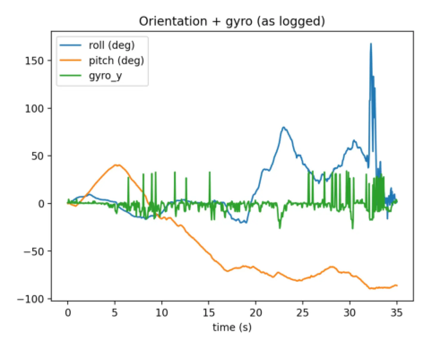
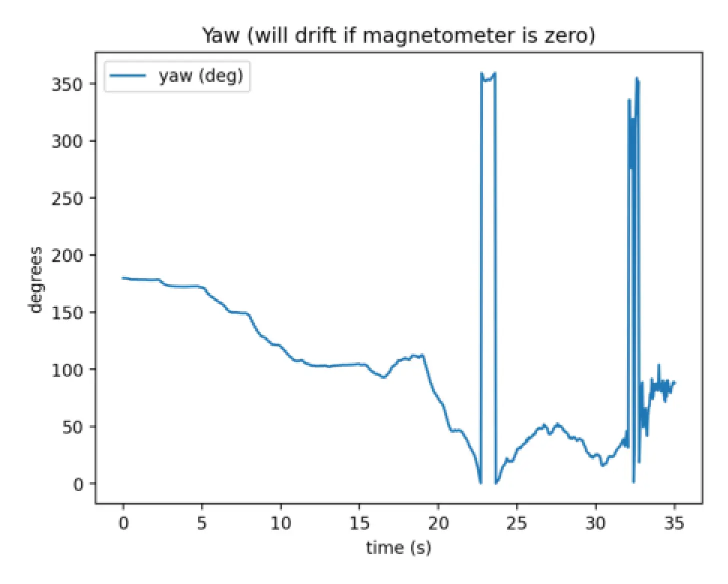
SENSOR FUSION
SPECIFICATIONS
- Primary Microcontroller: Teensy 4.1
- Secondary Microcontroller: ESP32
- Primary IMU (±16 g): ICM20948
- Secondary IMU (±200 g): ADXL375
- Barometer: BMP390
CONCLUSIONS
Given that majority of this project was a lot of self-taught work,
it gave me some extremely valuable technical lessons on:
Looking forward to start work on COOKED-3!
- PCB design (EasyEDA)
- Embedded systems
- Sensor integration
- Kalman filtering
- PID control
- C++
- The importance of sleep on cognitive function
Looking forward to start work on COOKED-3!
ACKNOWLEDGEMENTS
Super Awesome Rocketry Team:
- Emily Mikhail
- Turner Person
- Connor Petersen
- Mason Jones
- Eduardo Pina Lopez
GALLERY
© 2026 Terrence Andre San Gabriel